
Güzeltepe Mah. Mareşal Fevzi Çakmak Cad. No:116/1 Eyüp/İSTANBUL
0212 627 68 58
info@geosurvey.com.tr
We, as GEOSURVEY, dedicate ourselves to help mining and industrial projects with eco-friendly aspect. We turn the technologies, which reduces the environmental pollution, into the services in favor of sustainability and quality for natural life. We run our projects with this eco-friendly consciousness and certify the leak-tightness of the applications in an attempt not to have environmental waste, by performing final control and inspections with our professional technical team as well high-tech and certificated equipment. We enlarge the dimension of the geosynthetic products performance for your projects by providing the reasonable, fast and economical solutions.
Our vision is to be closely related to the latest technological innovations and contribute to provide the habitable environment for next generation by using high technologies.
Our mission is to give fastest feedbacks to your expectations by integrating our professional team and high technology.
We offer full services till the end, without sacrificing quality, in every step of your project with our accreditation and calibration certificated professional team and equipment in the field of supervisor services by responding American Society for Testing and Materials standards.

We provide all kind of Supervisorship and Expertise related to geosynthetics and also to control the systematical harmony by Liner Integrity test method on the completed geomembrane layer and to perform supervision and quality control test in the right place.
This method controls the integrity and non-damaged statue of the fields with completed geomembrane application according to ASTM D7953 (American Society for Testing and Materials). It detects simply and fast if there is any failure in the system by providing the quality control of enlarged leak-tightness systems in company with changing regulations.
Arc Testing Method: This test detects all 1mm holes on the geomembrane surface according to ASTM D7953, however studies show that this method can determine much smaller damages than 1mm. It is applied that a high-voltage power source sends current to geomembrane surface by means of probe fixed to a mechanism which technician can easily use. The current is consistently transferred to surface by running the probe on the geomembrane surface. It is concluded that the current makes arc with lower conducting layer by passing over the geomembrane in case of any irregularity (hole, torn, thinning etc.) on the geomembrane. At this stage, device alerts the technician by giving audio-visual signals. GEOSURVEY informs all damages detected on the scanned geomembrane surfaces to the repair crew by the means of written form and schedule. The repaired points are tested once again.
Advantages of Liner Integrity Test:
Responsibility: GEOSURVEY takes responsibility for control of field integrity along with routine test methods at the stage of geomembrane application and issues a certificate according to this. The potential damage detection, which is impossible to handle, on the black geomembrane is carried out without any problem thanks to inspection.
Low Cost: Comparing the cost of Arc (Integrity) test and the budget which is required to fund for fixing the problems because of leaks from potential damages on the geomembrane, it is obvious that the test cost is much less than repairing them.
It is practical and no installation required: This method is not required a permanent field installation. It is fast and reliable method in order to be sure if there is no damage after geomembrane application and to control the quality.
Fastness: A technician can approximately control 6.000 m2 application per day. Test duration is easily increased or decreased according to the project requirement and field condition.
We operate the progressing geosynthetic application (GCL, geomembrane, geotextile, drainage geocomposite, etc.) on your field with our experienced supervisors on behalf of you.
We carry out the tests of your geosynthetic applications on the field with our experienced team and calibration equipment.
✓ Inspection: We carry out the tests of your geosynthetic applications on the field with our experienced team and calibration equipment.
✓ Vacuum Test: According to ASTM D5641 standard, this method is applied on the repairing and reinforcement (patch) fields which is used the extrusion weld method.
✓ Air Pressure Test: According to ASTM D5820 standard, this method is used to test the sustainability for parallel twin welded fusion welding which is divided by an air channel.
✓ Welding Resistance (Tensiometer) Test: According to ASTM D4437 standard, this method is applied on the completed geomembrane panel welding or on the samples of testing welding before the main welding. It gives opportunity to show the quality result of welding resistance based on a numerical value as N/mm.


✓ Calibration procedures of all equipment in use
✓ Control of manufacturer test reports and laboratory test reporting of geosynthetic materials supplied within the scope of your project
✓ Daily logs of ongoing technical works within the scope of the project
✓ Logs of the quality control tests and final result report
✓ Leak-tightness control result report after Liner Integrity Test

Geosurvey also applies integrity test method for waterproofing buildings in accordance with the ASTM D7877 standard. Building foundation-underground wall applications and watertightness tests of high building terraces can be done quickly and safely. This method is used in areas where water testing cannot be performed. The watertightness test of applications made with synthetic and bituminous membranes, liquid membranes, spray application, HFA waterproofing systems can be performed with the integrity test method. Conductive materials such as cement-EPDM are not tested with this method. We also provide Expertise and Supervisorship services for all waterproofing tests made in the product and building types defined above. Please get information from our expert teams about which system-product groups can be tested.
Geosurvey is the regional distributor of Tinker Rasor. Please click for the products we are selling

WHAT IS DIPOLE TESTING?
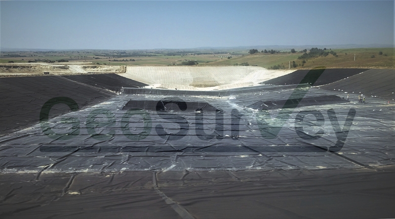
Maintaining the integrity of geosynthetic lining systems is critical for landfills or heap leach areas. Dipole Test, which is applied with equipment in accordance with ASTM D7007 standard, is a geoelectrical technique developed to determine the leakage locations of geomembranes coated with natural materials (clay, sand, gravel, etc.) with high precision. Especially in Mining Heap Leach projects, it is applied after the gravel layer placed on the top layer of HDPE geomembranes used as impermeability layer.
HOW DOES IT WORK?
Geosurvey experts create a test area work plan during the preliminary inspection of the site to be tested. In line with the plan, electrical sources are temporarily positioned in the area to be tested. Test technicians start the damage detection work in the test area with current monitoring sensors configured in accordance with ASTM D7007 standard. The detected damage points are reported to the project owner.
WHAT ARE THE ADVANTAGES?
It is possible to detect even 1cm2 leak points in different damage simulations without any additional damage to the geomembrane layer.
It is the most practical test method developed for the control of geomembranes covered with various natural materials such as gravel, soil and sand.
Leak locations are quickly detected without the need to add a permanent component to the area to be tested.
Research shows that the probability of damage to geosynthetic materials is very high when natural materials (gravel, etc.) are laid on geosynthetic materials. With the “Dipole Test” method, the impermeability function targeted in your project can be achieved safely after gravel paving.


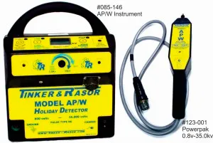
800 volts to 35,000 volts in 1 instrument
Features
800 volts to 35,000 volts in one instrument
Safety cutoff switch
LCD output Meter
Audible & Visual detecting holiday indicators
MIL-SPEC, locking Power-Pak cable
Open, Ergonomic design, reduces user fatigue
Integrated belt loop system
Portable
6v Rechargeable Battery
THREE YEAR WARRANTY
Multiple electrodes available (See Electrodes page for details)
Construction
Built for extreme environments
Rugged for field use
Power cutoff placed on Power-Pak
Longer Power-Pak cable
Form fitting design for wearing on hip or over the shoulder
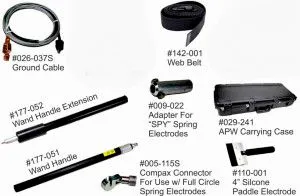
The Model AP/W comes complete in kit form, including:
Model AP/W instrument and battery
Power-Pak and 5' cable
20', 1/4 turn Locking Ground cable
Wand handle, 18", with full circle spring electrode connector
Wand extension handle, 18"
Battery charger, 110v or 240v
Belt (Adjustable for either waist of shoulder use)
Voltage adjusting screwdriver
Adapter to use "Spy" Spring Electrodes
MIL-SPEC, carrying case
One electrode* (Click here to choose your electrode)
Instructions Manual
Certificate of Calibration
The Model AP/W includes the integrated peak reading voltmeter, also used in the Model APS, to measure and display the output voltage being applied to the structure.
Other significant features include the unique T&R Safety Handle. The Safety Handle allows the user much more control over the instrument and does not allow the instrument to be left energized when unattended. This feature provides safety not only for the operator but also for all others sharing a job site.
The Model AP/W main instrument is worn on a belt, keeping most of the weight on the operator and not contributing to arm fatigue when used on tanks, floors, walls, or other non-pipe structures.
Of the new features, one of the most important is the safety switch. This trigger system provides greater job-site safety for both the operator and nearby personnel and is very easy to use. Simply release the trigger, and the instrument instantly turns off.
The handle must be held down on the grip to operate the instrument, and the unit is shut down immediately when the handle is released.
This feature will increase job site safety as an instrument cannot be left energized while unattended.
After setting the voltage, the instrument remembers the setting and the range, so the instrument can be turned on and off as much as necessary without requiring further adjustments.
The instrument is controlled by an electronics package contained within the water impenetrable cover of the instrument. All control switches are push button operations, with large operational areas, easy to manipulate while wearing gloves. Controls include On, Low and High voltage ranges, LCD voltmeter display, the voltage setting switch, Loud and Louder volume controls and the wand handle release button.
Just below the LCD voltmeter display is the visual alert for holiday indications. This alert is made of a cluster of "super bright" LED's that are easily seen in bright daylight conditions.
The voltage selection switch is located just above the LCD voltmeter display and is sealed from weather and dust by a screw cap. Using the supplied screwdriver, the dust cap is removed and voltages are set by turning the voltage selector as shown in the graphics. On the Low voltage range, select between 800 volts and 8,000 volts. On the High voltage range, select between 3,500 volts and 35,000 volts.
The LCD voltmeter display shows voltages in kilo-volts (kV). So, a voltage setting of 800 volts would be displayed as 0.8 and a voltage selection of 35,000 volts would be shown as 35.0.
*Electrode choice is made from the the Full Circle Spring Electrodes, 4" to 36" pipe diameters, or the Half Circle Spring Electrodes, 0.75" to 8" pipe diameters or Wire or Silicone-Rubber brush electrodes, 2" to 8" widths. You may choose one electrode per instrument, within the size ranges listed. Other sizes are available at a pro rated cost. Please call or e-mail for more information
| Application | Calibration |
|
|
|
Recommendation |
|
Specified and Approved on specs around the world Conforms to NACE International RP0188, RP0274, RP0490 |
|
|
|
|
|
|
|
|
|
|
| Environment | |
|
|
| Dimensions |
Mevcut Parçalar ve Aksesuarlar:

